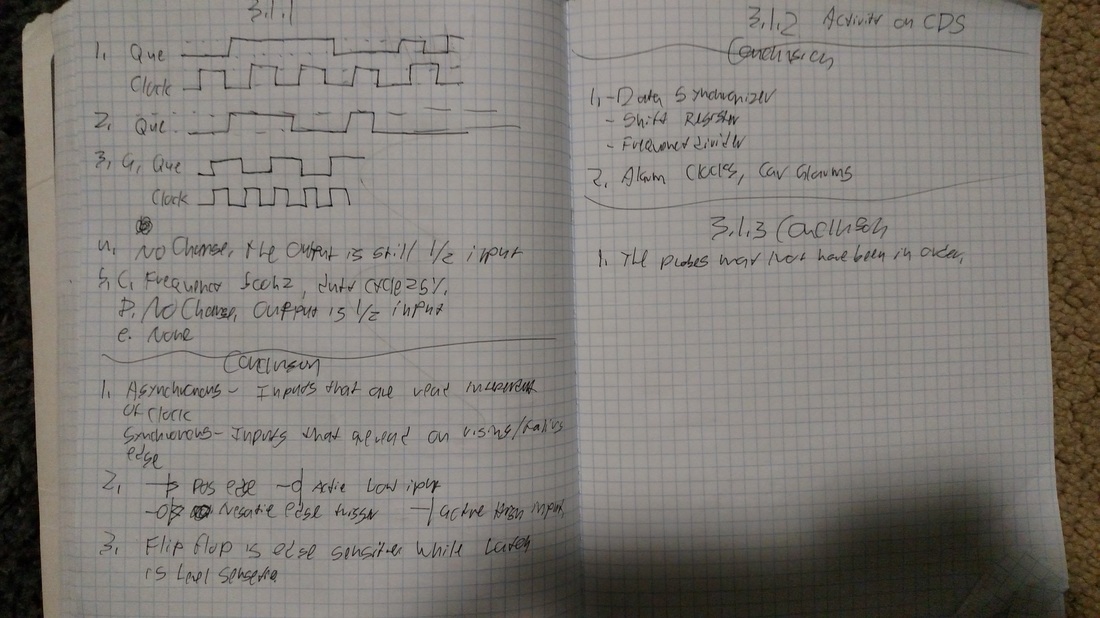
Activities 3.1.1, 2, and 3
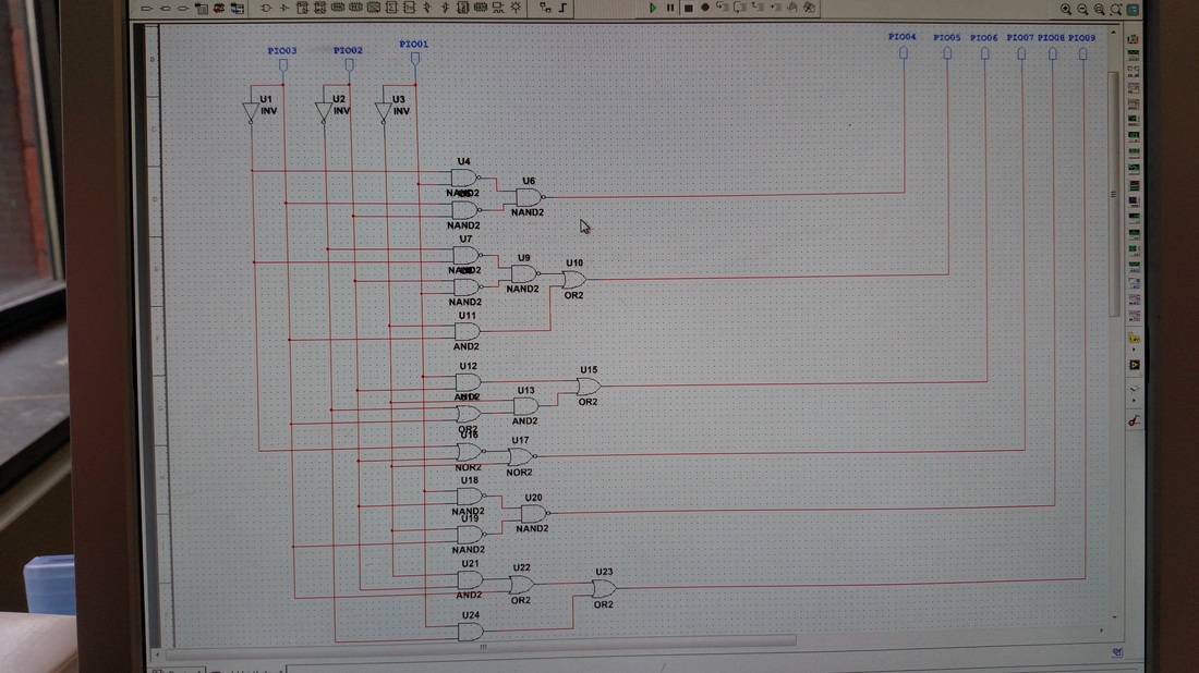
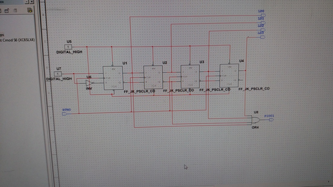
3.1.3 design images
|
|
|
2.4.1Circuit Design https://docs.google.com/document/d/1p6WskNUVWvWZ3D3UEjKMonctS8mxkxVXU0NAFX8NEy0/edit?usp=sharing Problem Statement Design a circuit that displays your birthdate in a mm-dd-yy format, displaying dashes in between the numbers. The numbers should display with a binary 3 bit counter for the three inputs. The output should be a seven segment display. Design Solution My design solution is the circuit that i have designed and uploaded. Conclusion I solved the problem by creating individual circuits for each display segment. This was an effective solution and i believe that i organized the solution very well. 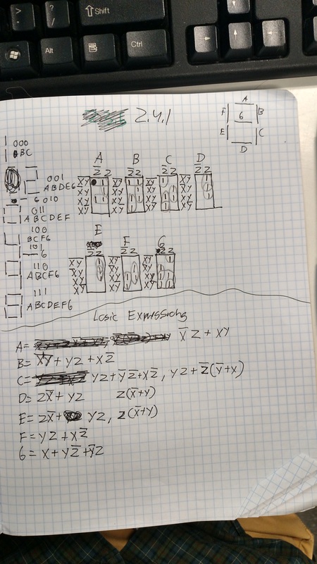 2.4.2  1. Look up the names and definitions for the following programmable logic acronyms: a. PLD: Poor Life Descision b. PAL: Police Athletic League c. GAL: Good and logic d. CPLD: Chidren Cry laughing dead e. FPGA: For poor get allowed . The evolution of programmable logic devices from the simple PALs of the late 1970s to the FPGAs of today is a classic example of Moore’s Law. What is Moore’s Law? (n.) The observation made in 1965 by GordonMoore, co-founder of Intel, that the number of transistors per square inch on integrated circuits had doubled every year since the integrated circuit was invented. Moore predicted that this trend would continue for the foreseeable future 2.4.3Conclusion
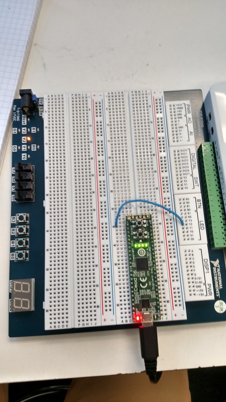
BuildConclusionConclusion:
1. The state machine design in this activity has four states and thus requires two state variables. If a design required eight states, how many state variables would be required? 4 2. What about sixteen states? 8 What is the relationship between the number of states and the number of state variables? It cuts it in half 3. If you simplified the logic expression for the three (or four) outputs correctly, the final expressions were not a function of the input EN. It will ALWAYS be the case that the outputs are not a function of the inputs. Why? Because EN simply tells the function to move to the next step 4. List three advantages of implementing sequential logic designs with programmable logic versus traditional discrete logic design (i.e., AOI, NAND, or NOR logic). requires less breadboarding, takes less time, more efficient Design ProblemDesign a combinational logic circuit that will monitor the copier’s three input sensors and activate both an LED and stop the feed motor whenever a paper jam is detected. The inputs from the three sensors (A, B, and C) and the output to the motor should be connected to four of the DMS’s general purpose I/O input pins. The clear signal should be connected to any of the DMS’s four pushbutton switches. The jam signal should be connected to any one of the DMS’s eight LEDs. Your design will require a few additional features that will allow VEX sensors and motors (which were designed for different voltage levels) to be controlled by the PLD. Design and logic simplification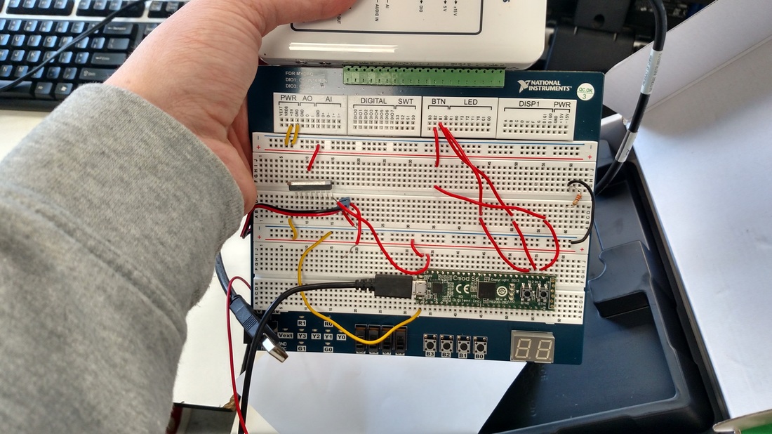 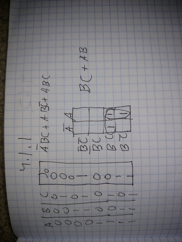 ConclusionThis project was not a success but in the end it did what it needed to do. Haderal and I could not get the vex limit switches to work and the full bridge driver. Because of this we had to resort to using the buttons on the breadboard to replace limit switches, and use a light to replace the motor turning on and off. The logic side of the project, which i created, worked flawlessly. It was a simple circuit comprised of 2 and gates and an or gate. The circuit was comprised of a simple logic circuit that triggered a flip flop if there was a jam. A reset switch would reset the flip flop, which had an output that would trigger the motor to stop or go.
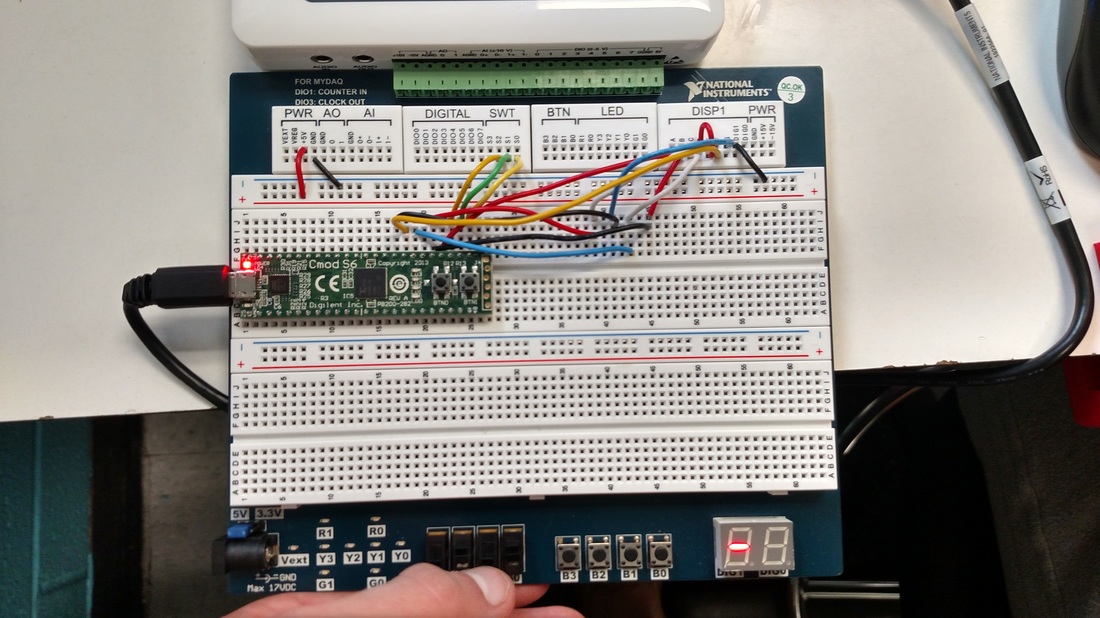
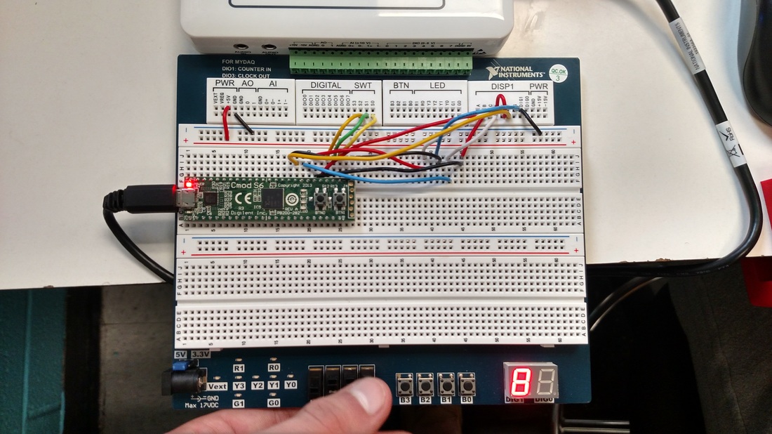
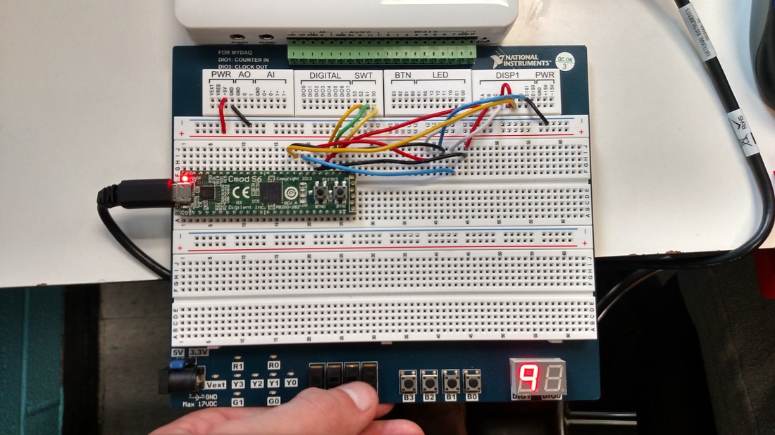
pROBLEM sTATEMENTIn this design problem, you will have the opportunity to draw together all of the concepts and skills that you have developed pertaining to the topic of synchronous counter design. You will design, simulate, and create a Sixty Second Timer. Design SolutionThis project was especially challenging. I was able to create the regular version of the circuit on multisim fairly easily, but i had lots of trouble converting the circuit to pld mode. I copied the circuit in its entirety, creating the exact same circuit on pld mode. For some reason, the ones place counter would cycle but it would not trigger the clk input of the tens place counter. It simply did not work at all until i used a different synchronous counter. Replacing the counter should not have changed anything at all in regards to how the circuit functioned, but the circuit suddenly worked after that. It was a good learning experience that taught me that even if you do things completely correctly, multisim still hates you.  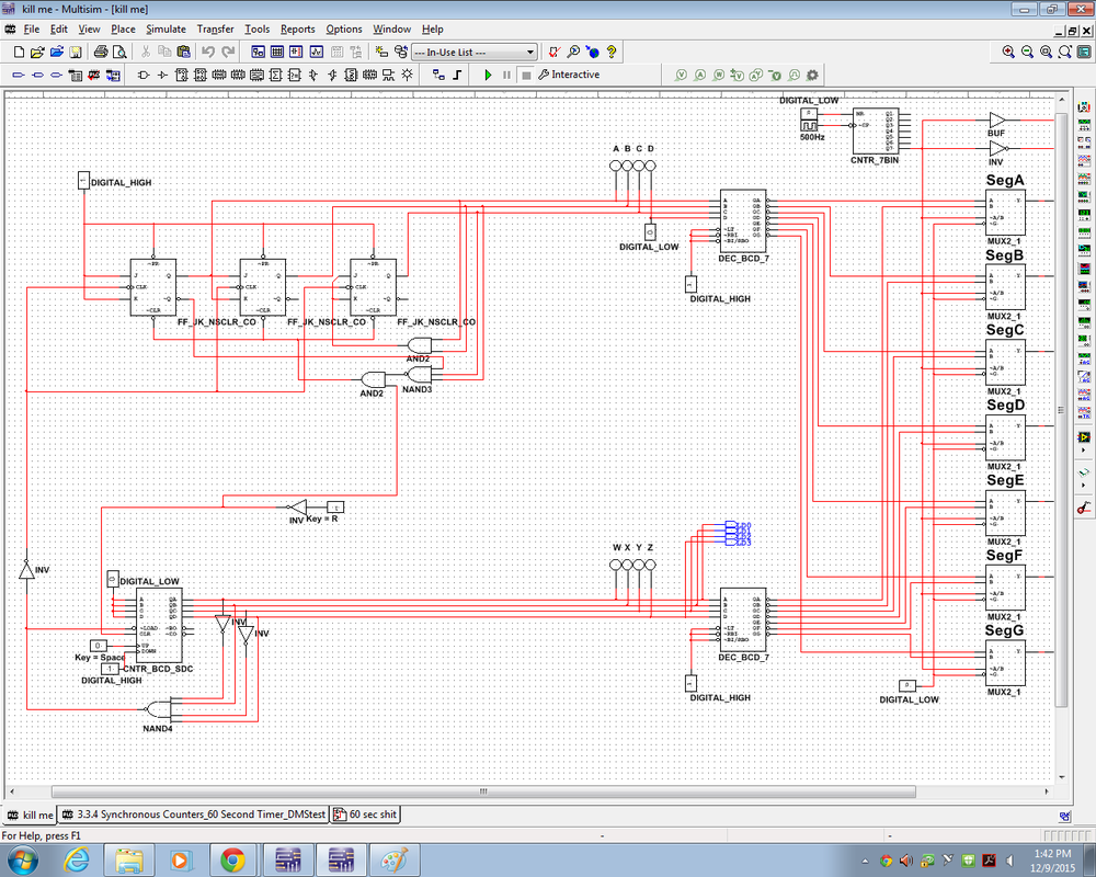 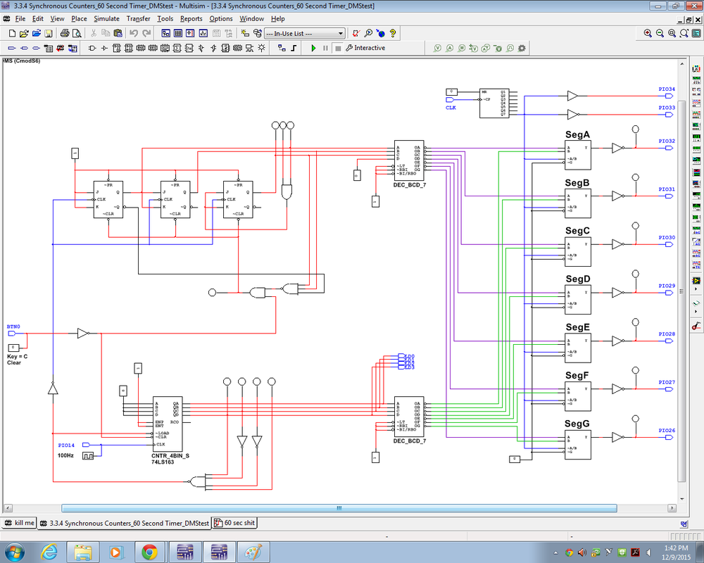 BuildBuilding this circuit with the aid of the pld was not hard. It required my to wire the corresponding outputs on the pld to the seven segment display inputs, and also wire dig0/1. I used a button for the clock input for ease of use. 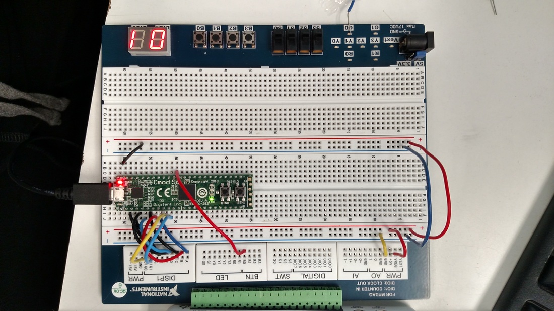 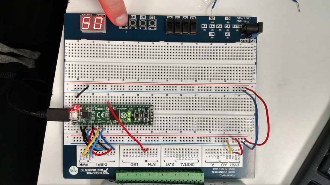 ConclusionThis project was incredibly stupid and stressful, because i had everything done right but my circuit still did not work. There was no reason my circuit should have not worked with the counter i was using because the reset/clk line was wired to the outputs of the ones place counter, making the type of counter used irrelevant. This problem probably added 2-3 days to me completing this project, leaving me hopelessly far behind in the class yet again. In the end this simple circuit should have been easy but led to me doing endless troubleshooting with no end in sight.
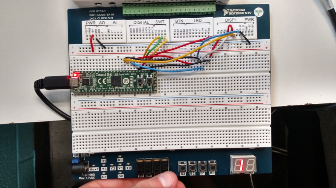
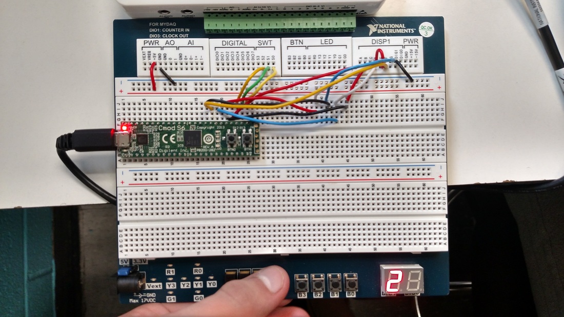
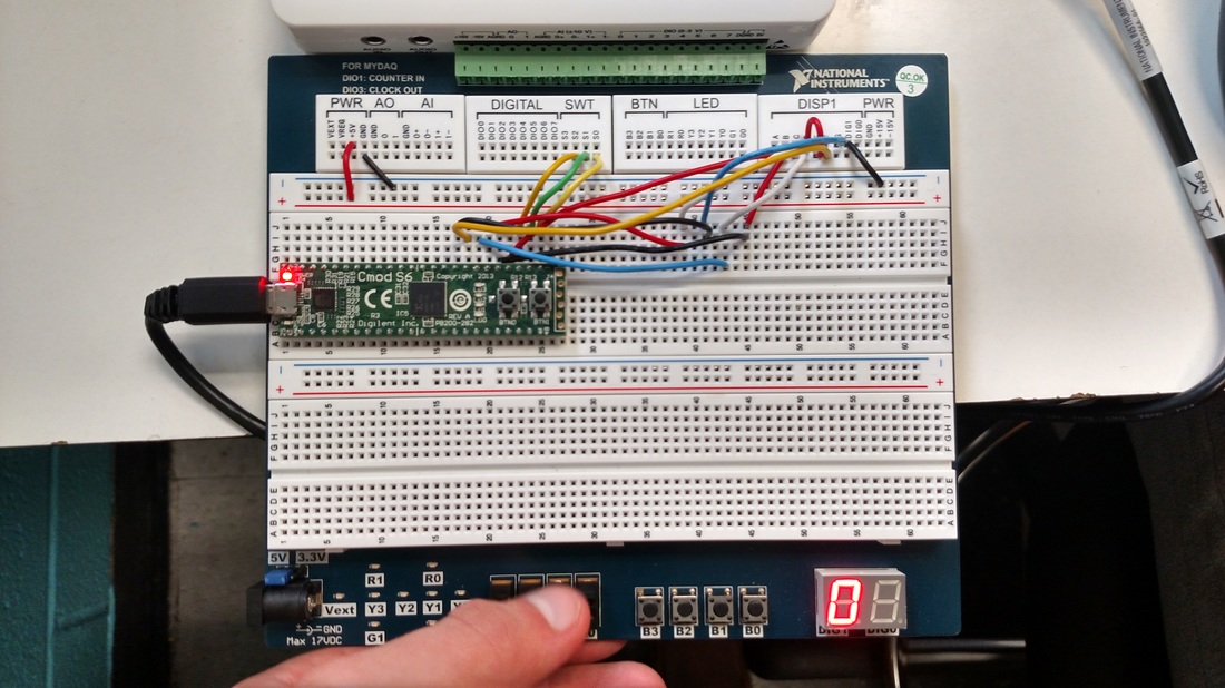
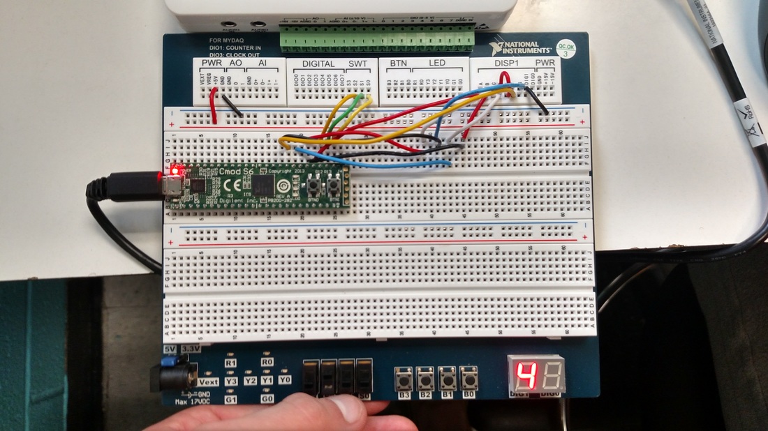
Problem StatementDesign a digital circuit that displays the count from 00 to 80. This design has two control inputs and two output displays. The two inputs are Next and Reset. The Next signal comes from a push-button switch that, when pressed, advances the display by one. The Reset signal, which is also a push-button switch, will reset the display to a count of 00. When the display reaches 80 the count will cease. (The employee at the deli counter takes a break and a new employee takes over the counter after the 80th customer is served.) Design Solution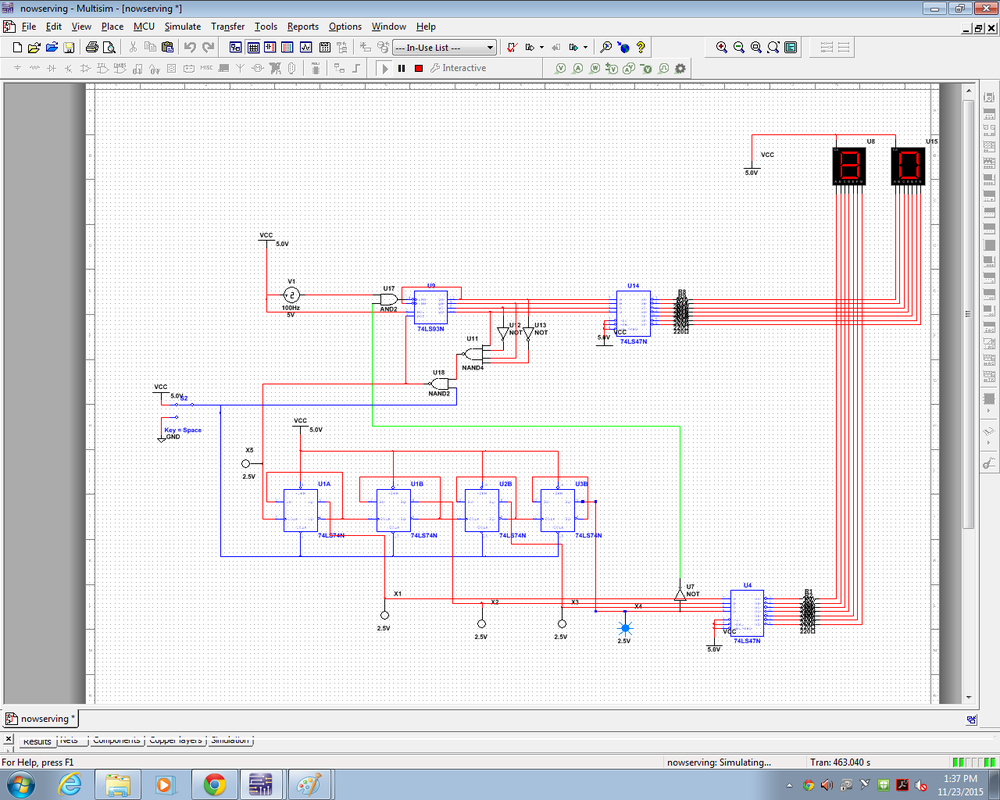 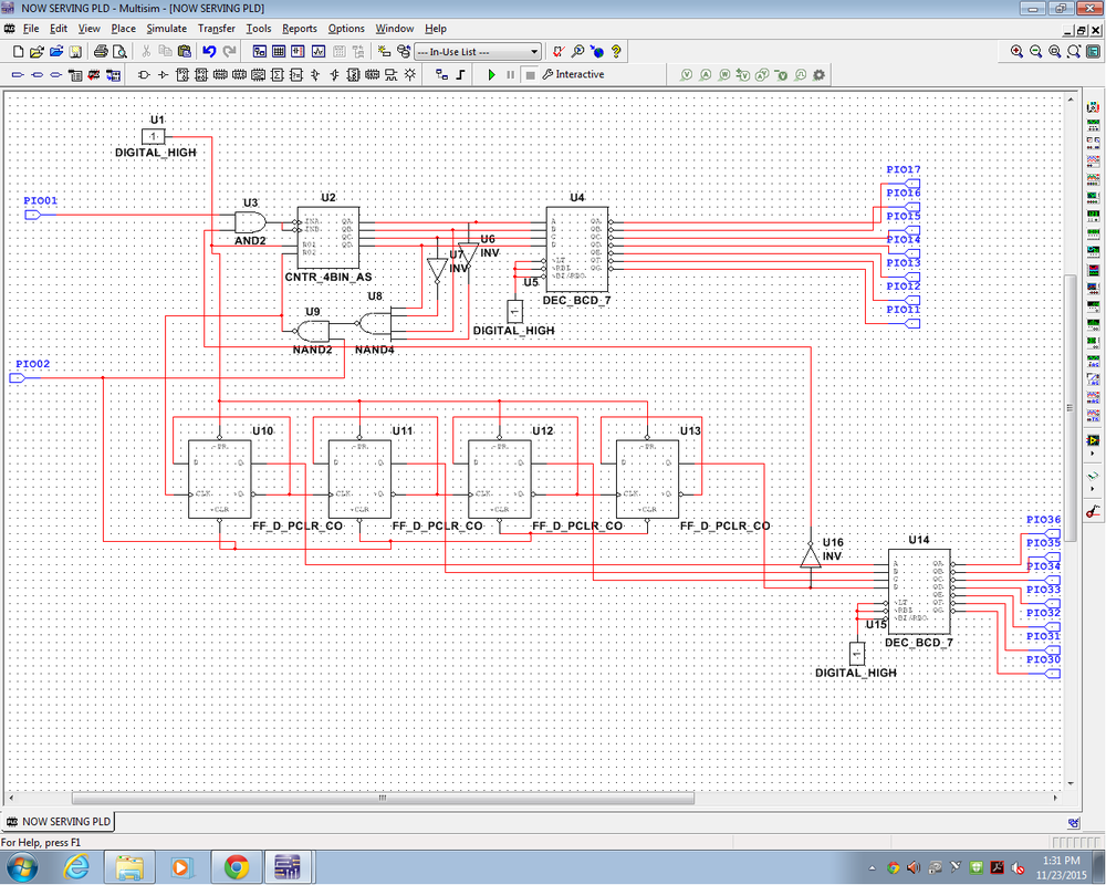 ConclusionThis project was probably the most challenging project we have done yet in this class. I decided to try to do the project without any outside help and it was very challenging. I solved the problem by using a 4 bit counter ic for the ones place and using a 4 bit counter made of D flip flops. The ones place counter is reset when the counter reaches 10. This reset action also advances the tens place counter. When the tens place counter reaches 8 the count is suspended until the reset switch is toggled. If i were to download my circuit to my pld i would have to include a multiplexer circuit that could toggle between the two output seven segment displays. I am very happy with the final product and it feels good to have it done.
Unit 1 completeToday i have completed unit 1! Hooray! I did very well on the test so i think i have mastered the concepts to the best of my abilities. Unit 1 was pretty hard and i think that the rest of the course will be harder.   As of today I have completed section 1.1. I feel that I have mastered the concepts as I have received a 95% grade on the end of section quiz. If there is one thing I need to brush up on it would be logic gates, as almost everything else in the section is review from POE. CDS is fun to use and I feel that I am good at using it. Below are diagrams showing the different logic gates and their corresponding truth tables. 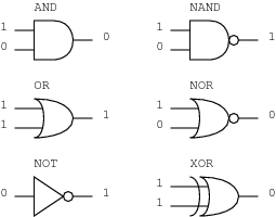  As of today I have mastered these skills:
K1 – Recognize safety hazards associated with electrical circuits and know the best practices of working safely in an electronics lab environment. K2 – Identify the equipment and know how to effectively use the equipment in an electronics lab. K3 – Know scientific notation, engineering notation, and System International (SI) notation. K4 – Know formulas for Ohm’s Law, Kirchhoff’s Voltage Law, and Kirchhoff’s Current Law. K5 – Know the characteristics of series and parallel sections of a circuit. K16 – Know the best practices of soldering and de-soldering components. Today I researched types of soldering and different soldering methods. Below is a site that i looked at.
http://www.aaroncake.net/electronics/solder.htm |